
The Lucent antenna also gave us a good indication that a signal could be carried over the trial distance and terrain, before we committed to building our own antenna.. We concluded that as long as we had line of sight, with minimal foliage in the path, that we could transmit between any two points in the Karekare area (easily up to ~4Km we needed). That turned out to be mostly true.
Antennas use the same language, as they are also dealing with vibrations. In the antenna case, the vibration is an electromagnetic wave rather than a sound wave in air molecules. The speed of electromagnetic radio signals is the speed of light, rather than the speed of sound. Light being an electromagnetic (radio) wave that we can see (Our eyes don't have antenna that can see other radio waves). For antennas, We don't refer to notes or pitch, but use the term "frequency". Frequency is measured in Hertz, though the older term, cycles per second, was more descriptive. The wavelength of a signal is the speed of light divided by the frequency, so, like sound, the wavelength gets shorter as the frequency increases, so our antennas get smaller. Radio signals also produce harmonics, which are dependent on the way we add the digital messages to the WiFi carrier (or center) frequency.
A wire antenna is like a vibrating string or tuning fork. The wire is cut to the wavelength (more often a sub-harmonic of the wavelength) and will resonate when there is a radio signal arriving, and this will produce an electrical signal in the wire that the radio can use. The reverse happens when we transmit.
A waveguide antenna is a Pan Pipe equivalent. The internal dimensions of the waveguide antenna are made to be resonant at the frequency of interest, as are the slots we cut in the face of the waveguide.
A wire antenna resonates with the electrical part of the electromagnetic wave, and the slots in the waveguide resonate with the magnetic part of the electromagnetic wave. The electric and magnetic parts of the electomagnetic wave are at right angles to each other, so a horizontal wire is equivalent to a vertical slot. Antennas will work with frequencies close to the carrier signals frequency. How efficently, depends on the antenna design. This is refered to as the antennas bandwidth.
Our original antennas are all horizontally polarized (the electric component being horizontal, and the magnetic compenent vertical). The newer commercial basestations have dual polarization, also having a vertically polarized patch antenna. Having both polarization does increase bandwidth, so is an advantage.
It should also be noted that the speed of light in wire is lower than the speed in air. The material around the wire (even copper oxide) effects this. This is represented by the velocity factor, which is the percentage of the speed of light in the antenna or cable compared to the speed of light in air. The velocity factor of copper wire is about 0.95 times the speed in air, so a copper antenna will be about 5% shorter. The diameter of the wire is also a factor. The sound analagy breaks down here, though sound does travel faster in denser materials, and is different when the material is under tension. For radio waves, the effect is due to induced movement of electrons in the material. It is also the reason light appears to be slower in glass or water, than in air. The induced signal gets added to the arriving signal, and the resulting wave has a slower speed than light in air.
Antennas also have impedance, as do the cables connecting them to the WiFi radio. Impedance is the AC equivalent of DC resistance, and both are measured in Ohms. For radio waves, this is usually 50 Ohms for the radio, and ~377 Ohmns for air. Physically, this manifests as the ratio of the electic and magnetic fields. A mismatch between between the impedance of the Antenna (including the cable) and the impedance that the transmitter expects will result in a reflection of some of the transmitted energy back to the transmitter. At visual wavelengths, this effect can be seen as the reflection of light off of a window. About 4% of the light is reflected, due to the difference between the impedance of air and glass. At high power levels, this reflected energy can cause damage to the transmitter, so testing should be done at low transmit levels. A mismatched impedance reduces the efficiency for both transmitting and receiving.
Testing the efficiency of receiving, by using a remote WiFi signal, will give you a good indication of the transmitting efficiency of the antenna. Antennas are mostly symmetric for receive and transmit. Getting a perfect match between the antenna and radio is unusual. There are antenna testers (SWR meters (Standing Wave Ratio)), that can be used to tell how much of the transmitted signal is being reflected. There are also testers that measure the impedance and bandwidth (though many testers do not work at WiFi frequencies). An SWR below 1.5 is the goal, with Ratio of 1 being ideal. Some antenna need a matching network, but none of our designs use them.
Cable loss is a significant factor too. Cable loss at 2.4GHz is significant, and much worse at 5GHz, so keep antenna cables very short. You can find cable loss from the manufacturers web sites, and there are some online calculators. LMR100 cable is thin, and you should keep the length very short, as it has high loss per meter. LMR200 has about half the loss of LMR100. LMR400 has about half the loss of LMR200, but is quite thick. We did use up to 2m of LMR400, but eventually connected to our waveguides with right angle N-connectors, directly to our WiFi routers, or used very short LMR100 (100mm) jumpers to the WiFi Routers.
Cable loss will also affect the SWR reading of a test, as the reflected wave will experience loss coming back down the cable. The SWR will then look to be lower than it really is. Testing the antenna, with a short calibrated cable, and the separately testing the feed cable, using a dummy 50 Ohm resister, instead of the antenna, is a good approach. Though most of you wont have the testing equipment to do this.
Keep the antenna away from other metal objects. At least a wavelength is advisable, which for 2.4GHz is only 123mm, so not very far. You also want to minimise reflections from behind, or from objects in the signal path. I did have a location with a large semicircle of rock behind the house, and despite getting a good signal, the wifi wouldn't work due to reflections causing interference. Moving the antenna only a small distance solved the problem. We have also found pine trees near the signal path, to act like tinsel reflecting the radio wave (their Pine needles being about the length of a 2.4GHz antenna).
|
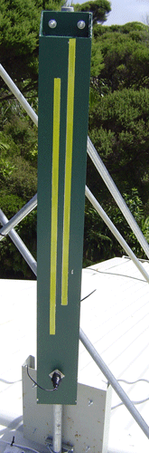
8+8 Slotted waveguideWe were looking for a high gain omnidirectional antenna for our access points. Searching the net for antenna designs we came across Trevor Marshall's waveguides web site. This has a good description of the slotted waveguide design he built and several references to other designs including Paul Wade's (W1GHZ) online "Microwave Antenna Book". Using Paul's Excel spreadsheet and looking at Trevor's and others designs (such as Rob Clark's downpipe), we built a test 8+8 slotted waveguide (eight slots each side) from a length of 100x50 (x3mm thick) aluminium rectangular hollow box section. This proved to have a good 360 degree signal, Testing against the Lucent yagi, the slotted antenna had an excellent signal at our 3Km test point. We did find a blind spot at 45 degrees to the antenna and about 20 degrees below it (understandable, the gain is achieve through restricting the vertical signal coverage). Rotating the antenna brought the signal up to a usable level. We will look at adding "wings" to the antenna to see if this evens out the coverage. |
 |
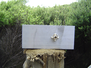
8 Single sided Slotted waveguideWe were also looking for a high gain 180 degree antenna for our central site. Having lots of spare 100x50 aluminuim, we built a test single sided 8 slot waveguide This proved to have a good 180 degree signal, Testing against the Lucent yagi, the slotted antenna still had an excellent signal at 3.5Km. |
These have a really good gain, and are simple to make. We now use these at nearly all the client ends, mounting them inside the router box (see picture.). We make the backing plate wider than is strickly necessary, so that it fits in the box better, and glue them in place. We are using them over 3km paths, with a single sided 8 slot waveguide at the far end. We have also used them at both ends, as point to point relays, over a 2.5km path, with 32mW tx power.
 | What we built (14dBi) |
 |
Looking for a cheap and easy to construct client antenna, we came across, amongst others, tin can (circular waveguides)
and brick (rectangular waveguides) designs. We built a rectangular waveguide from an offcut of the 8+8 slotted
waveguide and tested it against the Lucent yagi and the 8+8 slotted waveguide. It proved to have a usable range somewhere
around 2km. With the 1/4wave dipole probe, it failed at our 3Km test point, but was working just before 2Km. With the cone probe, it was still working well at 3km.
Details of Rectangular Waveguide built |
I came across the Horn design and will trial something like it. The horn is increasing the gain of the simple waveguide.
 |
The Lucent Yagi antenna is superior to the simple waveguide, so we went looking for simple to build yagi designs. We have yet to construct one, but came across Andrew Hakman's and Darren Fulton's site, which has links to others. I don't think we will build any of these now. The bicircles have the same gain, are smaller and simpler to make. |
I'm not sure how much use this will be in our situation, but this is has reasonably good gain for its size. An example is on Tim's web page.
Helicals use circular polarization, left or right, rather than vertical or horizontal. They will also happily work with a vertical or horizontal source (in reality the signal that arrives at the receiver is probable somewhere between anyway). They can be really useful in situations where there are reflected signals arriving at the antenna causing interference. A reflected circular polarized signal reverses its polarization and is therefore much weaker compared to the direct signal of the same polarization as the antenna. An example of a homebuild helical and another good site by Dr. Remco den Besten, PA3FYM