Building the 8+8 Slotted Waveguide
We used 100mm x 50mm rectangular hollow box section aluminium with 3mm thick walls.
This gives us an internal size of 94mm x 44mm. We chose to build the antenna for
2.442GHz, or channel 7, as this is close to the center of the 13 channels available
to us (US designs use channel 6 (2.437Ghz), as they have 11 channels). The internal width (the wide side), determines the operating frequency. The internal height (the narrow side) determines the impedance. We used
Rob Clark's
5 wavelength design over Trevor Marshall's
4.75 wavelength design simply because we could cut the 5 wavelength design down to get the
4.75 wavelength one if our first try didn't work. Trevor's design also has wider slots and
our slots could be made wider if we messed them up too much. We used
Paul Wade's
spreadsheet (Slotantenna.xls)to calculate
the slot sizes and placement (The "Improved from Elliot" figures with a 2% reduction in slot
length for square ends (see his text)). I have included a key lengths calculator in the form below.
- The waveguide impedance drops rapidily from infinite at Te10 cut off, then becomes close to linear
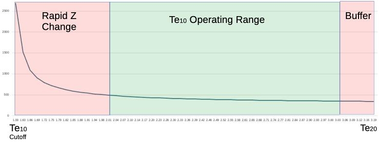
- Te10 Cut Off is the lowest frequency the waveguide will operate at.
- At the next mode frequency, the waveguide will resonate differently, and at a different speed
(Next mode cut off is usually the Te20 mode, but if the width < 2 x Height, it becomes the Te01 mode)
- Operating Range is ~1.27 x Te10 Cut Off, up to 95% of the next mode Frequency
The low 27% of the range has a very rapidly changing impedance
Above 95% of the next mode, there is a danger of jumping to a different resonant mode.
The final product only needs to be accurate to about 1mm as this will only shift the frequency
within the range of the 802.11 spectrum. A smaller slot length will shift the frequency response
of that slot to a higher channel. A longer slot length will shift it down. Changes in the slot
spacing affects the vertical signal pattern. A smaller spacing (higher channel) results in
the lower channels having a slightly downward virtical pattern. A larger spacing (A lower channel)
will result in higher channels having a slightly upward tilted vertical pattern.
Slot width variation affect the frequency response.
The distance of each slot from the center
varies with design. I don't know what this affects. One design deliberately changes this distance
for each slot so as to reduce the side lobes of the vertical radiation pattern.
Methods and madness
I measured to .1mm using vernier callipers, on the assumption that errors in cutting might bring that
closer to the 1mm error mark. I measured and marked up the front first and used a square to copy the lines around the side
faces and onto the other side to ensure the slots on both faces lined up. I did in fact manage to get most slots cut
to a few tenths of a mm in length.
I used a drill press to make holes at either end of each slot and a hand held router with built on guide to cut
between them. I then used a file to square the ends of each slot and to clean the edges up.
I did discover how easily a router with can eat holes in 3mm aluminium. Some of my slots are slightly
wider in places. Tungsten router bits and tungsten circular saw blades will happily cut aluminium (and you).
Misc Notes
- 100mm is added to the bottom for mounting (included in form as the outside length).
- I used 3mm aluminium because the N-Socket is 3mm deep. The thickness also alters the
slot calculation, but I have no idea how (I'm told the slots would be smaller in length, but
I don't know what the exact realtionship is). People have successfully used much thinner material.
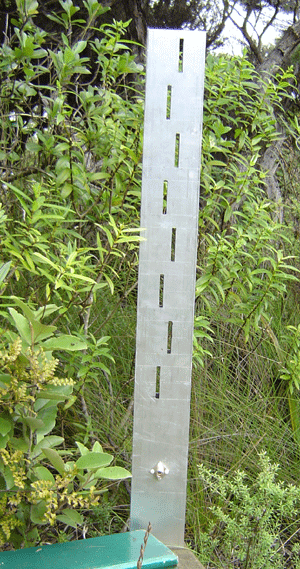
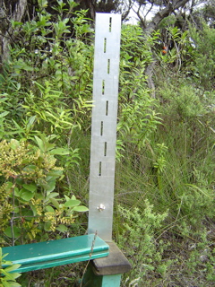
- The front slots and the back slots are positioned so you can see straight through them.
- The slots alternate left and right of center, but it doesn't matter which way the first one goes.
- We made the top cap from part of a 44mm offcut and filed it so it was a tight fit (I'm told this isn't that crtical).
- The other side of the offcut was used for bottom plate (We made it an L shape to help in fixing it) and used
the callipers to measure how far down the tube it needed to go.
- The probe is a 2mm diameter copper wire soldered into an N-Socket and cut 1/8λg, including the protruding bit of the N-Socket (Should be slightly longer).
Using a cone for a probe gave a much better SWR.
- The N-Socket is held down with nylon screws. I threaded the mounting holes. If you use metal screws,
use stainless steal ones and keep them short so they don't protrude into the cavity.
- Water in the antenna, or spider and insects will be a problem. One suggestion is to make the antenna
upside down and make small holes in the top plate to let the water out. Another is to cover the holes
with thin microwave transparent tape, such as Kapton (source 3M and expensive) or Mylar (also 3M, but a common polyester tape with an acrylic adhesive. Sometimes called Yellow Thermoset tape). Some people have used other tapes.
They should be as thin as possible and not heat up in the microwave.
Step by Step pictorial guide
 |
A view from the Front. Note that you can see through the slots (i.e they are
opposite one another).
|
For a step by step pictorial guide, follow me. The same contruction technique is common to both the single and double sided wave guide antenna.